+12V Ground Active command Inactive Fault / unknown
Selected motorSTOPPED
Brown lead0V / return*
Dark blue lead0V / return*
Window position50%
UP relayReleased
DOWN relayReleased
Wire / component inspector
Tap a highlighted wire or component in either schematic to inspect it.
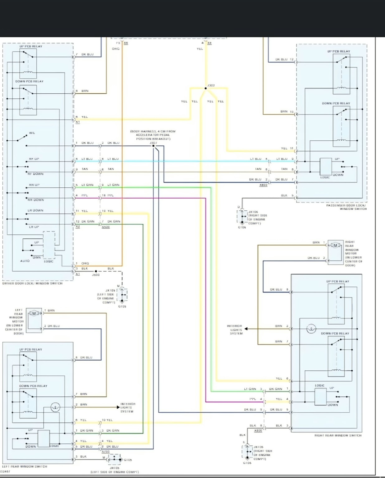
Training simulation, not a verified service diagnostic. The supplied factory image is low-resolution. Four motor locations and visible motor lead colors are identifiable; many command paths, supply contacts, and relay electrical states are approximations. The left front driver's motor is not visible as a separate motor in this diagram and may be represented in the master switch assembly. Verify voltages and connector cavity assignments against OEM service information before working on the vehicle.